Chi tiết thông tin đặc tính sản phẩm
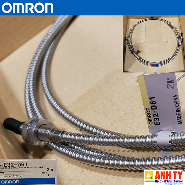
Cảm biến sợi quang Omron E32-DC200 | Diffuse reflective fiber Sensor
(khuếch tán phản xạ 900mm M6 2m)
Chức năng
Standard Installation
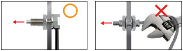
Threaded Models
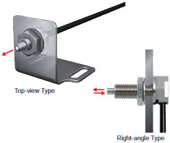
- Cấu hình tiêu chuẩn. Các Bộ sợi quang này được gắn vào một lỗ được khoan trong giá đỡ và được giữ chặt bằng các đai ốc./
Standard configuration. These Fiber Units are mounted into a hole drilled in a bracket and secured with nuts.
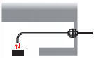
-Mô hình góc phải ngăn không cho cáp bị vướng vì cáp chạy dọc theo bề mặt lắp đặt./
The Right-angle Model prevents snagging on the cable because the cable runs along the mounting surface.
 Cylindrical Models
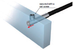
- Chèn ở nơi không gian hạn chế. (Được bảo vệ bằng vít định vị.)/
Inserted where space is limited. (Secured using a set screw.)
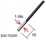
-Tăng cường tiết kiệm không gian bằng đầu vi sợi. (1 dia. × 10 mm)/
Ultramate space-saving by micro-fiber head. (1 dia. × 10 mm)
 Tiết kiệm không gian/ Saving Space
với kiểu dẹp/
Flat Models
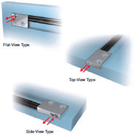
- Cấu hình mỏng để gắn trong không gian hạn chế./
Thin profile for mounting in limited spaces.
- Đếm trực tiếp mà không cần sử dụng giá đỡ đặc biệt./
Mounts directly without using special mounting brackets.
Kiểu có ống bọc ngoài (Phát hiện tầm gần)/ Sleeve Models (Close-range Detection)
- Kiểu cảm biến sợi quang có vỏ bọc ngoài cho phép phát hiện từ xa điểm lắp đặt để phát hiện các vật thể nhỏ ở cự ly gần ổn định./
Sleeve Fiber Units allow detection away from the point of installation for stable close-range detection of small objects.
- Hình dạng của vỏ bọc ngoài có thể được thay đổi tùy ý./
The shape of sleeve can be changed freely.
Cải thiện hiệu quả chùm tia/
Beam Improvements
Điểm nhỏ, phản xạ (Phát hiện đối tượng rất nhỏ)/
Small-Spot, Reflective (Minute Object Detection)
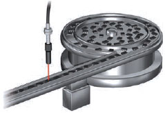
- Điểm nhỏ lý tưởng để phát hiện các vật thể nhỏ. Chọn Bộ sợi quang phù hợp nhất với kích thước phôi và khoảng cách lắp đặt (Tham khảo Thông tin Tham khảo để Chọn Mẫu)/
Small-spot is ideal for detecting minute objects. Select the Fiber Unit that is best suited for the workpiece size and installation distance (Refer to Reference Information for Model Selection).
- Có sẵn Bộ ống kính điểm thay đổi để thay đổi đường kính điểm mà không cần thay thế sợi quang. Đường kính điểm có thể được điều chỉnh theo kích thước của phôi bằng cách thay đổi chiều dài rút và khoảng cách cảm biến. Tham khảo biểu đồ sau, biểu đồ này cho thấy mối quan hệ giữa độ dài rút lại, khoảng cách tiêu cự và đường kính điểm./
Available with a variable-spot Lens Unit to change the spot diameter without replacing the fiber. The spot diameter can be adjusted according to the size of the workpiece by changing the withdrew length and sensing distance. Refer to the following graph, which shows the relation between the withdrew length, focal distance, and spot diameter.
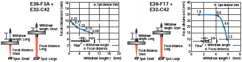
* Độ dài đã rút: Xấp xỉ. 1,3 đến 5,8 mm/
Withdrew length: Approx. 1.3 to 5.8 mm
Chùm công suất cao (Lắp đặt khoảng cách xa, Chống bụi)/
High-power Beam (Long-distance Installation, Dust-resistant)
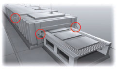
- Khoảng cách phát hiện tối đa mà không cần gắn ống kính: 20 m (E32-T17L). Thích hợp để phát hiện các vật thể lớn và sử dụng trong các cài đặt quy mô lớn./
Maximum sensing distance without attaching a Lens: 20 m (E32-T17L). Suitable for detection of large objects and for use in large-scale installations.
- Đủ mạnh mẽ để chống lại ảnh hưởng của bụi bẩn./
Powerful enough to resist the influences of dust and dirt.
- Ngoài các sản phẩm được liệt kê trên trang này, Ống kính có sẵn để mở rộng khoảng cách cảm biến./
In addition to the products listed on this page, Lenses are available to extend the sensing distance.
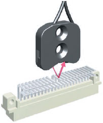
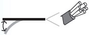
Chế độ xem hẹp (Phát hiện qua khe hở)/ Narrow View (Detection Across clearance)
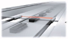
- Chùm tia nhỏ ngăn chặn phát hiện sai lệch ánh sáng do bị phản xạ từ các vật thể xung quanh./
The fine beam prevents false detection of light that is reflected off surrounding objects.
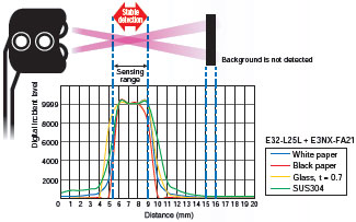
 Phát hiện không có nhiễu nền/ Detection without Background Interference
- Các đơn vị sợi quang này chỉ phát hiện các đối tượng trong phạm vi cảm biến. Các đối tượng trong nền nằm ngoài một điểm nhất định sẽ không được phát hiện. Chúng không dễ bị ảnh hưởng bởi chất liệu hoặc màu sắc của đối tượng cảm biến./
These Fiber Units detect only objects in the sensing range. Objects in the background that are located beyond a certain point are not detected. They are not easily affected by the material or color of the sensing object.
 Phát hiện đối tượng trong suốt/ Transparent Object Detection
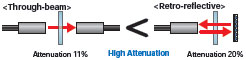
Phản xạ hồi quy/ Retro-reflective
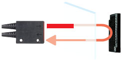
- Đơn vị sợi quang phản chiếu ngược là lý tưởng để phát hiện các vật thể trong suốt. Chùm sáng đi qua vật thể hai lần, mô hình này làm gián đoạn ánh sáng nhiều hơn so với mô hình Through-beam./
Retro-reflective Fiber Units are ideal for detecting transparent objects. The light beam passes through the object twice, this model interrupts light more than Through-beam model.
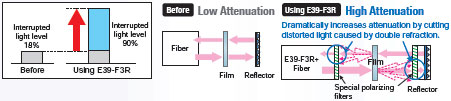
- Hiệu suất phát hiện tuyệt vời với các bộ phim trong suốt. (E32-C31 2M + E39-F3R). Bộ lọc được thiết kế đặc biệt loại bỏ ánh sáng không mong muốn, cho phép ánh sáng bị gián đoạn nhiều hơn đáng kể để phát hiện phim ổn định./
Excellent detection performance with transparent films. (E32-C31 2M + E39-F3R). The specially designed filter eliminates undesirable light, which allows significantly more light to be interrupted for stable detection of films.
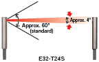
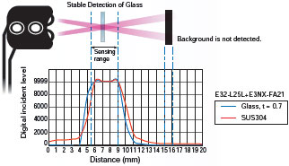
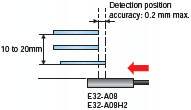
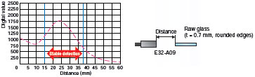
 Phản xạ giới hạn (Phát hiện kính)/ Limited-reflective (Glass Detection)
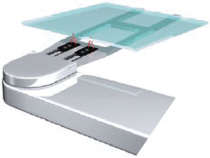
- Các đơn vị sợi quang này dựa trên một hệ thống quang học phản xạ giới hạn, nơi các trục ánh sáng phát ra và nhận ánh sáng giao nhau ở cùng một góc. Điều này cho phép phát hiện kính ổn định vì các Bộ phận sợi quang nhận được phản xạ đặc trưng của kính khi kính nằm trong phạm vi cảm biến./
These Fiber Units are based on a limited-reflective optical system where the emitting light and receiving light axes intersect at the same angle. This allows for stable detection of glass because the Fiber Units receives the specular reflection of the glass when the glass is in the sensing range.
 Không bị tác động bởi môi trường xung quanh/ Environmental Immunity
Chống hóa chất, chống dầu/ Chemical-resistant, Oil-resistant
- Các đơn vị sợi này được làm từ fluororesin để kháng hóa chất./
These Fiber Units are made from fluororesin for resistance to chemicals.
Dữ liệu kháng hóa chất cho Fluororesin (Tham khảo)/
Chemical-resistant Data for Fluororesin (Reference)
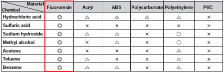
Lưu ý: Kết quả phụ thuộc vào nồng độ./
Note: Results depend on concentration.
Chống uốn, chống ngắt kết nối/ Bending-resistant, Disconnection-resistant
- Có khả năng chịu được một triệu lần uốn cong lặp lại./
Capable of withstanding one million repeated bends.
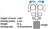
- Một số lượng lớn các sợi mịn độc lập đảm bảo tính linh hoạt tốt. Thích hợp để sử dụng trên các bộ phận chuyển động mà không dễ dàng bị vỡ./
A large number of independent fine fibers ensures good flexibility. Suitable for use on moving parts without easily breaking.
- Ống xoắn ốc không gỉ bảo vệ có sẵn để bọc cáp quang để bảo vệ nó khỏi bị đứt ngẫu nhiên do va chạm hoặc va chạm./
Protective Stainless Spiral Tube is available for covering the fiber cable to protect it from accidental breaking due to snagging or shock.
Chống nóng/ Heat-resistant
- Sản phẩm đa dạng cho nhiệt độ từ 100 đến 350 ° C. Chọn model theo nhiệt độ chịu nhiệt.
Ứng dụng đặc biệt/ Special Applications
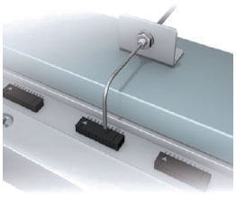
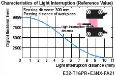
Chùm tia vùng (Phát hiện vùng)/ Area Beam (Area Detection)
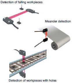
- Chùm tia diện tích là tối ưu để phát hiện phôi có vị trí không phù hợp, chẳng hạn như phôi rơi, hoặc phát hiện uốn khúc, hoặc phát hiện phôi có lỗ./ Area beams are optimum for detecting workpieces presented in inconsistent positions, such as falling workpieces, or for meander detection, or for detecting workpieces with holes.
- Đơn vị sợi quang này lý tưởng cho việc dò tìm uốn khúc vì nó xuất ra giá trị kỹ thuật số theo quan hệ tuyến tính với khoảng cách ánh sáng bị gián đoạn./ This Fiber Unit is ideal for meander detectin because it outputs the digital value in a linear relation to the interrupted light distance.
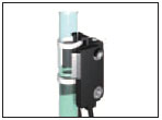
 Phát hiện mức chất lỏng/ Liquid-level Detection
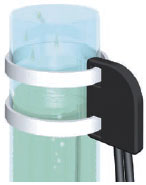
- Đơn vị sợi quang để phát hiện mức chất lỏng có hai loại: để gắn ống và tiếp xúc với chất lỏng./
Fiber Units for detecting liquid levels are available in two types: for tube mounting and liquid contact.
Các kiểu lắp ống/ Tube-mounting Types
Phát hiện mức chất lỏng bên trong các ống trong suốt. Quấn Thiết bị Sợi quang vào một ống có dây đeo./
Detect the liquid level inside transparent tubes. Strap the Fiber Unit to a tube with band.
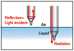
 Loại tiếp xúc chất lỏng/ Liquid-contact Type
- Phát hiện mức chất lỏng bằng cách tiếp xúc trực tiếp với chất lỏng./ Detect the liquid level by direct contact with the liquid.
- Kiểu này có khả năng kháng hóa chất tuyệt vời vì Bộ sợi quang được bao phủ bởi fluororesin./ This model has excellent chemical-resistance because the Fiber Unit is covered in fluororesin.
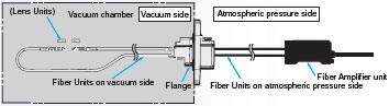
 Kháng chân không/ Vacuum-resistant
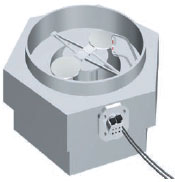
- Có thể được sử dụng dưới chân không cao lên đến 10-5 Pa./
Can be used under high vacuums of up to 10-5 Pa.
- Có sẵn trong các mô hình có khả năng chịu nhiệt lên đến 120 hoặc 200°C./
Available in models with heat resistant up to 120 or 200°C.
Ví dụ về cấu hình để sử dụng trong chân không/ Configuration Example for using under vacuum
FPD, chất bán dẫn và pin mặt trời (phản xạ có giới hạn)/
FPD, Semiconductors, and Solar Cells (Limited-reflective)
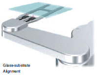 Căn chỉnh nền kính/ Glass-substrate Alignment
- Độ chính xác vị trí phát hiện: tối đa 0,2 mm./
Detection position accuracy: 0.2 mm max.
Không thay đổi vị trí phát hiện ngay cả khi khoảng cách phát hiện thay đổi./
No variation in detection positions even if the sensing distance changes.
- Nghiêng phôi không ảnh hưởng đến việc dò tìm./
Tilting workpiece does not affect detection.
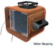
Bản đồ nền thủy tinh/ Glass-substrate Mapping
Có thể phát hiện ổn định ngay cả đối với các bề mặt cong khó phát hiện./
Stable detection is possible even for difficult-to-detect curved surfaces.
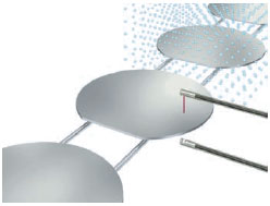
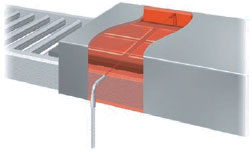
Phát hiện sự hiện diện của kính trong quy trình ướt/ Glass Presence Detection in Wet Processes
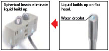
- Phát hiện không tiếp xúc ổn định ngay cả với kính cong vênh./
Stable non-contact detection even with warped glass.
- Các đầu hình cầu đảm bảo phát hiện ổn định mà không bị ảnh hưởng bởi chất lỏng./
The spherical heads ensure stable detection without being influenced by liquid.
FPD, Chất bán dẫn và Tế bào Mặt trời (Chùm xuyên qua)/ FPD, Semiconductors, and Solar Cells (Through-beam)
 Lập bản đồ Wafer/ Wafer Mapping
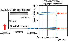
- Thiết kế mỏng cho phép dễ dàng lắp vào cánh tay robot./
Thin-profile design enables easy mounting on robot arms.
- Dễ dàng điều chỉnh trục quang học./
Easy to adjust optical axis.
(Sai số căn chỉnh điển hình giữa trục cơ và trục quang học chỉ ± 0,1 °.)/
(Typical alignment error between mechanical and optical axes is only ±0.1°.)
- Phát hiện wafer đáng tin cậy, ngay cả khi xếp chồng gần nhau./
Reliably wafer detection, even when stacked closely together.
Thông số kỹ thuật
Standard Installation
Threaded Models
Through-beam Fiber Units
Sensing
direction
(Aperture
angle) |
Size |
Appearance
(mm) |
Bending
radius
of cable |
Sensing distance (mm) |
Optical axis
diameter
(minimum
sensing
object) |
Models |
| E3X-HD |
E3NX-FA |
Rightangle
(Approx. 60°) |
M4 |
IP67 |
Flexible,
R1 |
GIGA: 2,000
HS: 700
ST: 1,000
SHS: 280 |
GIGA: 3,000
HS: 1,050
ST: 1,500
SHS: 280 |
1 dia.
(5 μm dia./
2 μm dia.) |
E32-T11N 2M |
Top-view
(Approx. 60°) |
IP67 |
E32-T11R 2M |
Top-view
(Approx. 15°) |
IP50 |
R25 |
GIGA: 4,000 *
HS: 2,700
ST: 4,000 *
SHS: 1,080 |
GIGA: 4,000 *
HS: 4,000 *
ST: 4,000 *
SHS: 1,080 |
2.3 dia.
(0.1 dia./
0.03 dia.) |
E32-LT11 2M |
Flexible,
R1 |
GIGA: 2,000
HS: 2,300
ST: 3,500
SHS: 920 |
GIGA: 4,000 *
HS: 3,450
ST: 4,000 *
SHS: 920 |
E32-LT11R 2M |
* The optical fiber is 2 m long on each side, so the sensing distance is 4,000 mm.
Note:
1. The following mode names and response times apply to the modes given in the Sensing distance column.
[E3X-HD] GIGA: Giga-power mode (16 ms), HS: High-speed mode (250 μs), ST: Standard mode (1 ms), and SHS: Super-high-speed mode (NPN output: 50 μs, PNP output: 55 μs)
[E3NX-FA] GIGA: Giga-power mode (16 ms), HS: High-speed mode (250 μs), ST: Standard mode (1 ms), and SHS: Super-high-speed mode (30 μs)
2. The values for the minimum sensing object are reference values that indicate values obtained in standard mode with the sensing distance and sensitivity set to the optimum values. The first value is for the E3X-HD and the second value is for the E3NX-FA.
3. The sensing distances for E3NX-FA are values for E3NX-FA[] models. The distances for E3NX-FAH[] infrared models are different.
Reflective Fiber Units
Sensing
direction
(Aperture
angle) |
Size |
Appearance
(mm) |
Bending
radius
of cable |
Sensing distance (mm) |
Optical axis
diameter
(minimum
sensing
object) |
Models |
| E3X-HD |
E3NX-FA |
Right-angle
(Approx. 60°) |
M3 |
Coaxial
IP67 |
Flexible,
R4 |
GIGA: 110
HS: 46
ST: 50
SHS: 14 |
GIGA: 160
HS: 69
ST: 75
SHS: 14 |
(5 μm dia./
2 μm dia.) |
E32-C31N 2M |
| M6 |
Coaxial
IP67 |
GIGA: 780
HS: 220
ST: 350
SHS: 100 |
GIGA: 1,170
HS: 340
ST: 520
SHS: 100 |
E32-C91N 2M |
Top-view
(Approx. 60°) |
M3 |
IP67 |
Flexible,
R1 |
GIGA: 140
HS: 40
ST: 60
SHS: 16 |
GIGA: 210
HS: 60
ST: 90
SHS: 16 |
E32-D21R 2M |
Coaxial
IP67 |
R25 |
GIGA: 330
HS: 100
ST: 150
SHS: 44 |
GIGA: 490
HS: 150
ST: 220
SHS: 44 |
E32-C31 2M |
Coaxial
IP67 |
R10 |
E32-C31M 1M |
| M4 |
IP67 |
Flexible,
R1 |
GIGA: 140
HS: 40
ST: 60
SHS: 16 |
GIGA: 210
HS: 60
ST: 90
SHS: 16 |
E32-D211R 2M |
| M6 |
IP67 |
GIGA: 840
HS: 240
ST: 350
SHS: 100 |
GIGA: 1,260
HS: 360
ST: 520
SHS: 100 |
E32-D11R 2M |
Coaxial
IP67 |
R25 |
GIGA: 1,400
HS: 400
ST: 600
SHS: 180 |
GIGA: 2,100
HS: 600
ST: 900
SHS: 180 |
E32-CC200 2M |
Top-view
(Approx. 15°) |
M6 |
IP50 |
R25 |
GIGA: 860
HS: 250
ST: 360
SHS: 110 |
GIGA: 1,290
HS: 370
ST: 540
SHS: 110 |
(1 dia./
0.03 dia.) |
E32-LD11 2M |
Flexible,
R1 |
GIGA: 840
HS: 240
ST: 350
SHS: 100 |
GIGA: 1,260
HS: 360
ST: 520
SHS: 100 |
E32-LD11R 2M |
Note
1. The following mode names and response times apply to the modes given in the Sensing distance column.
[E3X-HD] GIGA: Giga-power mode (16 ms), HS: High-speed mode (250 μs), ST: Standard mode (1 ms), and SHS: Super-high-speed mode (NPN output: 50 μs, PNP output: 55 μs)
[E3NX-FA] GIGA: Giga-power mode (16 ms), HS: High-speed mode (250 μs), ST: Standard mode (1 ms), and SHS: Super-high-speed mode (30 μs)
2. The values for the minimum sensing object are reference values that indicate values obtained in standard mode with the sensing distance and sensitivity set to the optimum values. The first value is for the E3X-HD and the second value is for the E3NX-FA.
3. The sensing distances for Reflective Fiber Units are for white paper. (The sensing distance for the E32-LD11 2M/ E32-LD11R 2M are for glossy white paper.)
4. The sensing distances for E3NX-FA are values for E3NX-FA[] models. The distances for E3NX-FAH[] infrared models are different.
Cylindrical Models
Through-beam Fiber Units
| Size |
Sensing
direction |
Appearance
(mm) |
Bending
radius
of cable |
Sensing distance (mm) |
Optical axis
diameter
(minimum
sensing
object) |
Models |
| E3X-HD |
E3NX-FA |
1
dia. |
Top-View |
IP67 |
Flexible,
R1 |
GIGA: 450
HS: 150
ST: 250
SHS: 60 |
GIGA: 670
HS: 220
ST: 370
SHS: 60 |
0.5 dia.
(5 μm dia./
2 μm dia.) |
E32-T223R 2M |
1.5
dia. |
IP67 |
Bend-
resistant,
R4 |
GIGA: 680
HS: 220
ST: 400
SHS: 90 |
GIGA: 1,020
HS: 330
ST: 600
SHS: 90 |
E32-T22B 2M |
3
dia. |
IP67 |
Flexible,
R1 |
GIGA: 2,000
HS: 700
ST: 1,000
SHS: 280 |
GIGA: 3,000
HS: 1,050
ST: 1,500
SHS: 280 |
1 dia.
(5 μm dia./
2 μm dia.) |
E32-T12R 2M |
| Side-View |
IP67 |
GIGA: 750
HS: 260
ST: 450
SHS: 100 |
GIGA: 1,120
HS: 390
ST: 670
SHS: 100 |
E32-T14LR 2M |
Note
1. The following mode names and response times apply to the modes given in the Sensing distance column.
[E3X-HD] GIGA: Giga-power mode (16 ms), HS: High-speed mode (250 μs), ST: Standard mode (1 ms), and SHS: Super-high-speed mode (NPN output: 50 μs, PNP output: 55 μs)
[E3NX-FA] GIGA: Giga-power mode (16 ms), HS: High-speed mode (250 μs), ST: Standard mode (1 ms), and SHS: Super-high-speed mode (30 μs)
2. The values for the minimum sensing object are reference values that indicate values obtained in standard mode with the sensing distance and sensitivity set to the optimum values. The first value is for the E3X-HD and the second value is for the E3NX-FA.
3. The sensing distances for E3NX-FA are values for E3NX-FA[] models. The distances for E3NX-FAH[] infrared models are different.
Reflective Fiber Units
| Size |
Sensing
direction |
Appearance
(mm) |
Bending
radius
of cable |
Sensing distance (mm) |
Optical axis
diameter
(minimum
sensing
object) |
Models |
| E3X-HD |
E3NX-FA |
| 1.5 dia. |
Top-View |
IP67 |
Bend-
resistant,
R4 |
GIGA: 140
HS: 40
ST: 60
SHS: 16 |
GIGA: 210
HS: 60
ST: 90
SHS: 16 |
(5 μm dia./
2 μm dia.) |
E32-D22B 2M |
1.5 dia.
+
0.5 dia. |
The sleeve
cannot be bent.
IP67 |
R4 |
GIGA: 28
HS: 8
ST: 12
SHS: 4 |
GIGA: 42
HS: 12
ST: 18
SHS: 4 |
E32-D43M 1M |
| 3 dia. |
IP67 |
Flexible,
R1 |
GIGA: 140
HS: 40
ST: 60
SHS: 16 |
GIGA: 210
HS: 60
ST: 90
SHS: 16 |
E32-D22R 2M |
IP67 |
Bend-
resistant,
R4 |
GIGA: 300
HS: 90
ST: 140
SHS: 40 |
GIGA: 450
HS: 130
ST: 210
SHS: 40 |
E32-D221B 2M |
Coaxial
IP67 |
R25 |
GIGA: 700
HS: 200
ST: 300
SHS: 90 |
GIGA: 1,050
HS: 300
ST: 450
SHS: 90 |
E32-D32L 2M |
3 dia.
+
0.8 dia. |
The sleeve
cannot be bent.
IP67 |
GIGA: 70
HS: 20
ST: 30
SHS: 8 |
GIGA: 100
HS: 30
ST: 45
SHS: 8 |
E32-D33 2M |
Note
1. The following mode names and response times apply to the modes given in the Sensing distance column.
[E3X-HD] GIGA: Giga-power mode (16 ms), HS: High-speed mode (250 μs), ST: Standard mode (1 ms), and SHS: Super-high-speed mode (NPN output: 50 μs, PNP output: 55 μs)
[E3NX-FA] GIGA: Giga-power mode (16 ms), HS: High-speed mode (250 μs), ST: Standard mode (1 ms), and SHS: Super-high-speed mode (30 μs)
2. The values for the minimum sensing object are reference values that indicate values obtained in standard mode with the sensing distance and sensitivity set to the optimum values. The first value is for the E3X-HD and the second value is for the E3NX-FA.
3. The sensing distances for Reflective Fiber Units are for white paper.
4. The sensing distances for E3NX-FA are values for E3NX-FA[] models. The distances for E3NX-FAH[] infrared models are different.
Saving Space
Flat Models
Through-beam Fiber Units
Sensing
direction |
Appearance
(mm) |
Bending
radius
of cable |
Sensing distance (mm) |
Optical axis
diameter
(minimum
sensing
object) |
Models |
| E3X-HD |
E3NX-FA |
| Top-View |
IP67 |
Flexible,
R1 |
GIGA: 2,000
HS: 700
ST: 1,000
SHS: 280 |
GIGA: 3,000
HS: 1,050
ST: 1,500
SHS: 280 |
1 dia.
(5 μm dia./
2 μm dia.) |
E32-T15XR 2M |
| Side-View |
IP67 |
GIGA: 750
HS: 260
ST: 450
SHS: 100 |
GIGA: 1,120
HS: 390
ST: 670
SHS: 100 |
E32-T15YR 2M |
| Flat-View |
IP67 |
E32-T15ZR 2M |
IP40 |
GIGA: 2,400
HS: 800
ST: 1,200
SHS: 30 |
GIGA: 3,600
HS: 1,200
ST: 1,800
SHS: 300 |
3 dia.
(0.1 dia./
0.03 dia.) |
E32-LT35Z 2M |
Reflective Fiber Units
Sensing
direction |
Appearance
(mm) |
Bending
radius
of cable |
Sensing distance (mm) |
Optical axis
diameter
(minimum
sensing
object) |
Models |
| E3X-HD |
E3NX-FA |
| Top-View |
IP67 |
Flexible,
R1 |
GIGA: 840
HS: 240
ST: 350
SHS: 100 |
GIGA: 1,260
HS: 360
ST: 520
SHS: 100 |
(5 μm dia./
2 μm dia.) |
E32-D15XR 2M |
| Side-View |
IP67 |


 dienelectrics@gmail.com
 0909186879
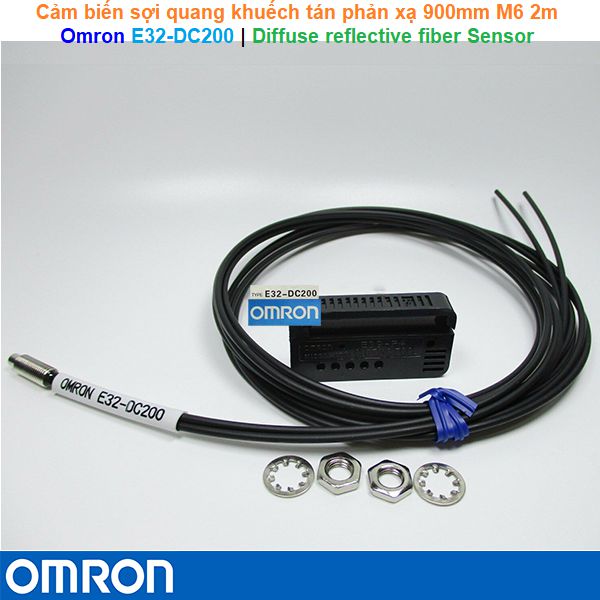
 2,468
2,468